Gear Load Distribution Measurements [LDM]
Astute - Gear Alignment Systems
Identify & Quantify Misalignment
High Sampling Rate
Low Power Mode
Measurements to ISO-6336
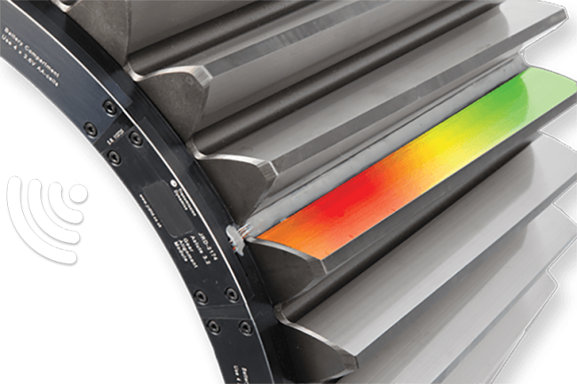
Precise Gear Alignment Assessment through Load Intensity Distribution Measurements

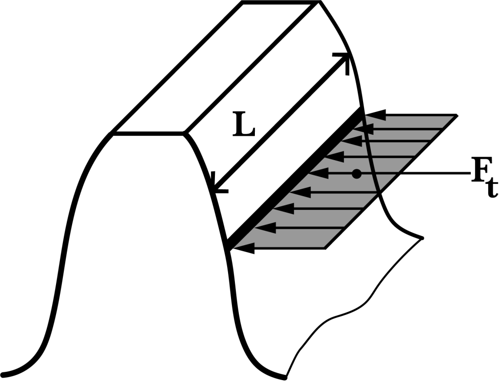
When it comes to assessing and quantifying gear misalignment, precision is paramount. The load intensity distribution across gear faces provides invaluable insights into the health and alignment of these critical components. Among various methods available, using strain gauges emerges as the most accurate and reliable approach for this crucial task. Strain gauges, meticulously bonded to the roots of gear teeth, are strategically placed to capture the subtlest nuances in load distribution during each mesh cycle. This placement ensures that the strain gauges respond precisely to the load applied, enabling them to detect even the slightest deviations from the ideal alignment.
As gears rotate and mesh, they experience dynamic changes in load distribution due to factors such as torque, speed, and the weight of rotating components. These variations can be indicative of misalignment issues, which, if left unaddressed, can lead to accelerated wear, reduced efficiency, and, ultimately, system failures. By measuring load intensity distribution using strain gauges, engineers and maintenance professionals gain unparalleled visibility into the intricate mechanics of gear interactions.
This data allows for a comprehensive assessment of gear alignment, enabling early detection of misalignment issues and facilitating timely corrective actions. In essence, load intensity distribution measurements using strain gauges serve as the gold standard in gear alignment analysis. Their precision and sensitivity empower professionals to proactively address misalignment concerns, ensuring the longevity, efficiency, and reliability of gear systems in a wide range of industrial applications.
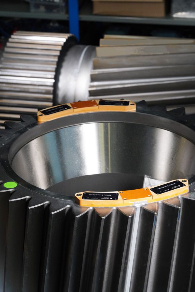
Our Gear Alignment System Enables:
Identification & Quantification
Our system offers the capability to not only identify but also precisely quantify the extent of gear misalignment, providing engineers with critical data for informed decision-making and corrective actions.
Plotting Load Distribution Curve
Our innovation leverages wireless technology and advanced sensors to offer a cutting-edge solution. It enables real-time monitoring and analysis of gearbox health, providing you with crucial insights into performance and potential issues.
Face Load Distribution Factors
With our system, engineers can plot a comprehensive load distribution curve that visually represents how loads are distributed across gear faces during operation. This curve serves as a graphical representation of the dynamic forces at play, aiding in the assessment of gear health and alignment.
Load Sharing Factors
In complex gear systems involving multiple paths, such as epicyclic, double helix, and dual tandem systems, our system enables the evaluation of load sharing factors denoted as Kγ. Kγ accounts for the maldistribution of load among these various paths, offering insights into how loads are shared and balanced within intricate gear mechanisms. This data is invaluable for optimising gear systems and ensuring uniform load distribution for enhanced durability and efficiency.
Using the acquired data, the gear tooth micro-geometry can be optimised to:
Reduce Gear Noise
Reduce Transmission Error
Improve Gear Safety Factors
Eliminate Gear Damage
Gear Alignment System Uses:
Validation
Our system serves as a robust tool for gear validation, providing engineers with precise data to confirm the alignment and performance of gear systems in real-world applications
Troubleshooting
When issues arise, our system becomes an invaluable asset for troubleshooting, allowing engineers to pinpoint misalignment or irregularities swiftly and accurately, minimising downtime.
Condition Monitoring
As part of a proactive maintenance strategy, our system excels in condition monitoring by continuously assessing gear health, detecting misalignment, and ensuring optimal performance over extended periods.
Some of our clients:


Incorrect gear microgeometry design
Manufacturing tolerance issues
Causes of Gear Misalignment
There are many causes of misalignment, both static and dynamic.
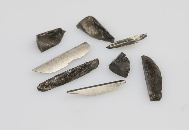
Gearbox case distortion
Assembly issues
Issues with bearing design (clearances) or bearing wear
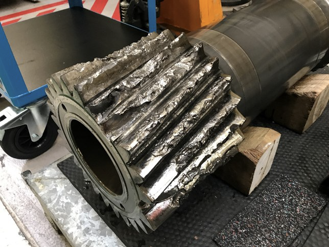
Issues with Gear Alignment include:
Reduction in gear tooth fatigue life
Failure due to tooth breakage
Surface failures including pitting, scoring or scuffing
Example Applications:
 In wind gearbox applications, our system provides critical gear alignment data, enhancing reliability and efficiency in renewable energy production.
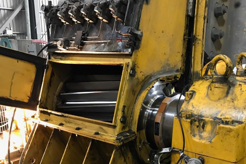
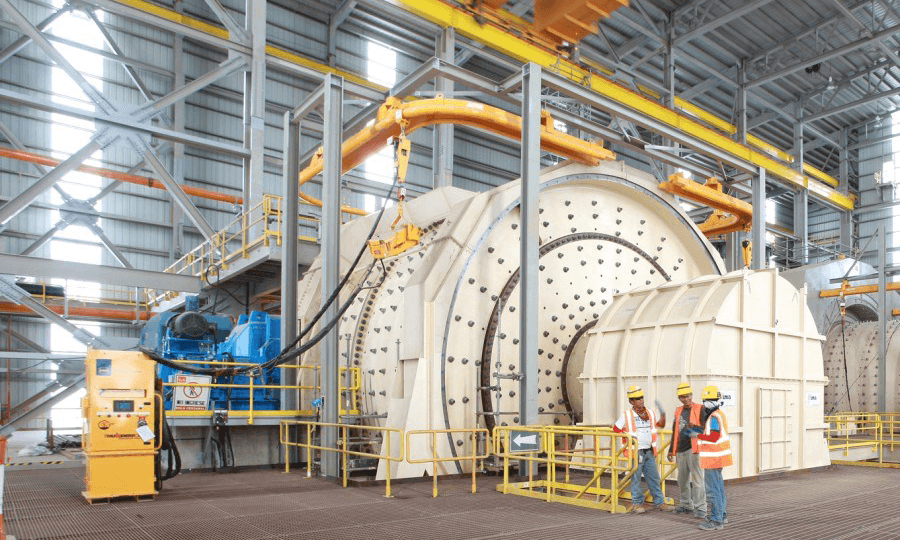 Our system ensures precise gear alignment in mining SAG mills, minimising downtime and maintenance costs in mineral processing.
 Our product ensures precise gear alignment in naval propulsion systems, guaranteeing optimal performance and longevity at sea.
 In naval propulsion, our system delivers exceptional gear alignment solutions, supporting the reliability and efficiency of marine propulsion systems.
Our Gear Alignment Design and Manufacture Process
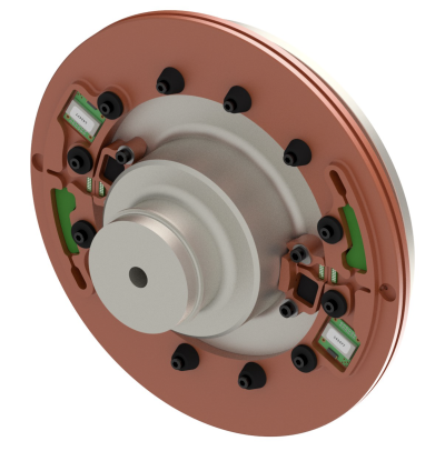
1.
Instrumentation design
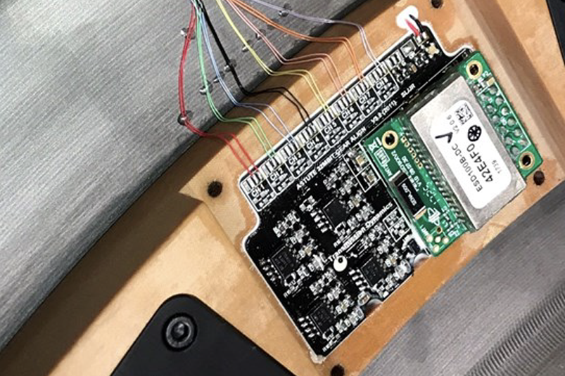
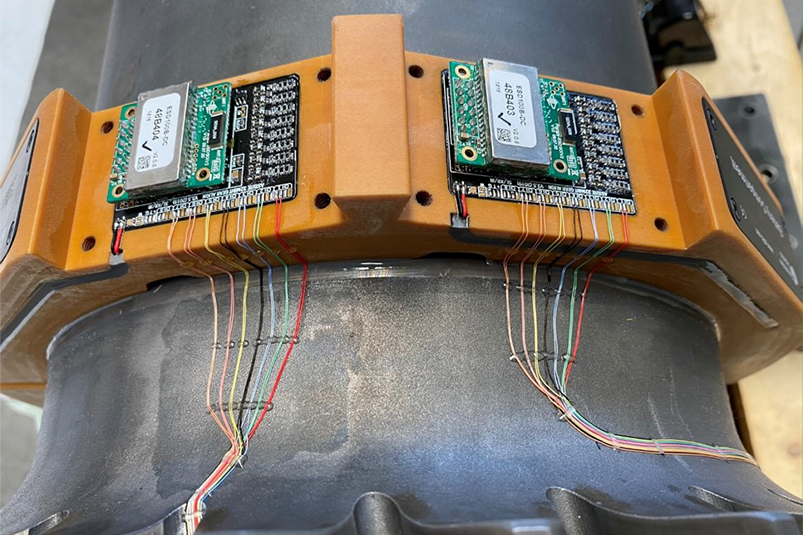
The system is designed to suit the client’s requirements including: the gear geometry, the available space envelope and duration of measurements required.
2.
Manufacture of instrumentation
The instrumentation is manufactured in-house using our CNC machines and electronics Pick-and-Place machine.

3.
Installation
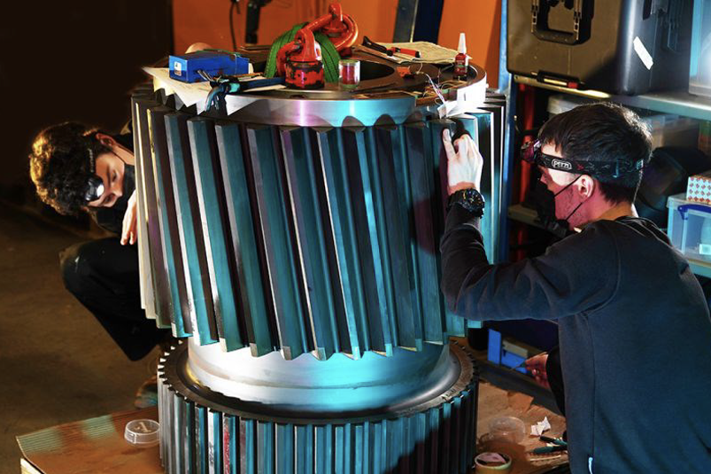
Typically the client would send the gears to Transmission Dynamics premises for instrumentation, or Transmission Dynamics have dedicated field staff for performing installations at client sites.
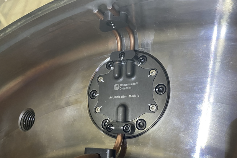
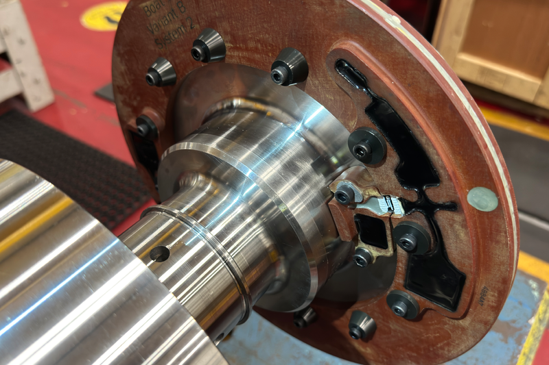
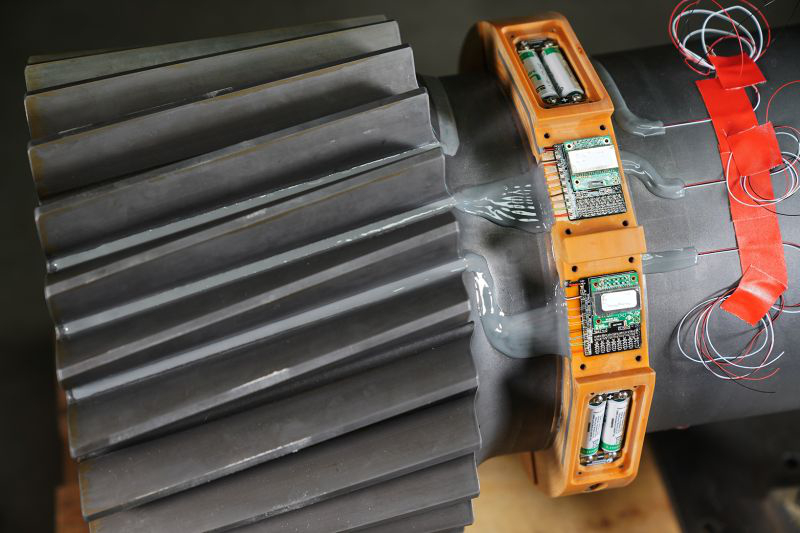
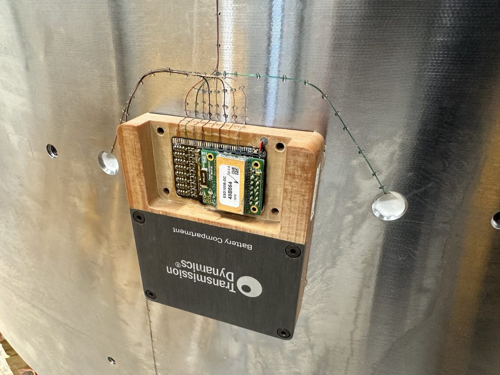
This involves gear root strain gauging, installation the instrumentation modules, and commissioning the system. Should the measurement campaign not take place for several weeks or months following installation, the modules can be set into user-configurable sleep mode.
4.
Data acquisition
The systems have a user-configurable sampling rate and logging duration enabling the client to acquire data from various load conditions during Factory Acceptance Testing (FAT).
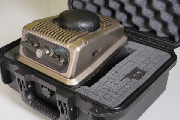
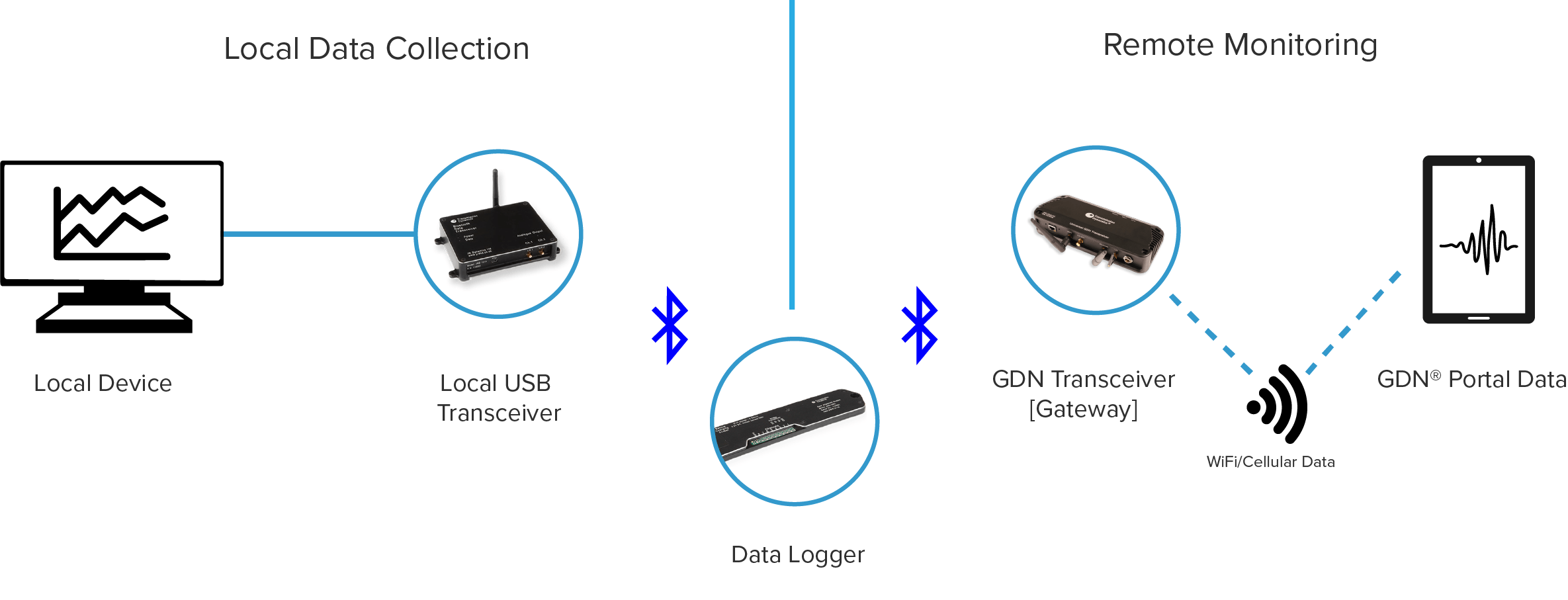
For condition monitoring, the system can be interfaced with Transmission Dynamics’ Global GDN Transceiver, enabling periodic data acquisition. The data can then be visualised and analysed remotely through our Global Data Network [GDN] portal.
5.
Data analysis
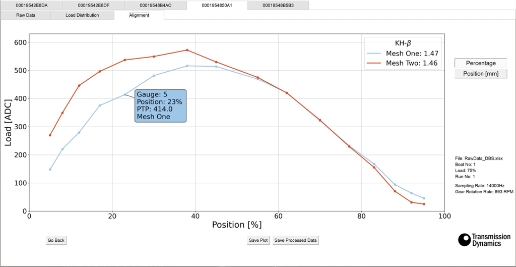
The data is then easily used to evaluate the Load Distribution across the gear face-width; enabling identification of any issues including direct evaluation of face-load distribution factors (KHβ and KFβ).
Our Gear Alignment System
Rotating Machinery Compatibility
- Systems designed for operation on rotating machinery.
Flexible Power Options for Logging
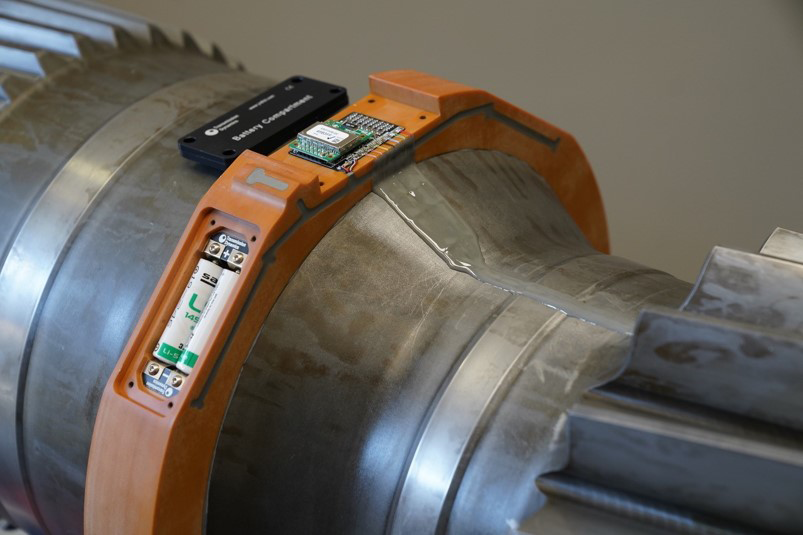
- Available as a battery powered or inductively powered system depending on duration and frequency of logging required.
View our “Measurement of deformation in gears” video on YouTube (opens in a new window)
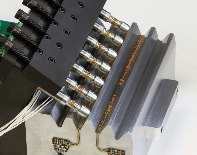
Our Sensors
The system offers a range of compelling benefits, making it an ideal choice for precision gear alignment and load measurement applications.
Extended Battery Life
Features an intelligent sleep mode that allows for several years of battery life, reducing maintenance requirements.
Customisable Sampling Rates
Allows users to adjust sampling rates, with options for simultaneous sampling at 14 kHz or higher rates for channel-by-channel analysis.
Multi-Channel Data Acquisition
Capable of acquiring data from up to 8 channels simultaneously, including a once-per-revolution shaft marker for precise measurements.
Flexible Bridge Configuration
Each channel can be configured as quarter, half, or full bridge, optimising measurement position resolution across the gear face-width, accommodating up to 32 axial positions.
Intuitive Software
Bespoke software offers easy adjustment of channel offset, data acquisition, and automatic misalignment evaluation, streamlining the analysis process.
Reliable Installations
Leveraging extensive experience in load measurement systems, it delivers compact and dependable installations.
Tailored Housings and Power Solutions
Designed to suit specific applications, ensuring compatibility and functionality.
Low Profile Installation
Enables installation in applications with minimal tip-to-root clearances, as low as 0.5mm.
In-House Manufacturing
System design and manufacturing in-house enable rapid deployment, meeting unique application needs efficiently.
The Gear Alignment System Data Flow: from Sensor to Analytics
Part of the Transmission Dynamics Ecosystem
PANDAS-V®
This advanced system revolutionises rail industry practices by offering affordable and scalable remote condition monitoring solutions for electrified train pantographs and overhead lines. By addressing maintenance challenges and enhancing efficiency, PANDAS-V transforms rail operations and sets new standards for monitoring and maintenance in the industry.
Smart Oil Plug®
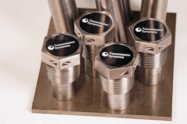
The Smart Oil Plug® is an innovative technology designed for the railroad industry, providing real-time monitoring of final drives and transmissions via wireless data transmission, detecting various parameters like temperature, vibrations, oil debris, and more, while offering extended maintenance intervals and global data access.

